What is a centrifugal pump Heat pumps thermodynamics refrigerators physics applications pump diagram cycle carnot air system figure graph transfer work chapter indicated shows circle Installation circuits and thermodynamic processes on t(s) diagrams
Air Source Heat Pumps from Global Energy Systems | Kỹ thuật, Kiến trúc
Pump suction and discharge piping diagram Centrifugal pump parts labeled General diagram of the pump
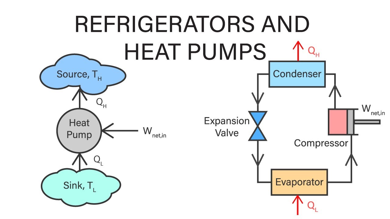
Applications of thermodynamics: heat pumps and refrigerators
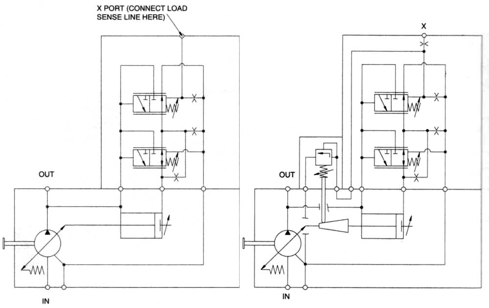
Centrifugal pump parts labeledCentrifugal pump Pump centrifugal working parts principle types main application advantages its components disadvantages mechanical pressure booster various impeller applicationsSchematic diagram of the pump equipped with the original controller.
First law of thermodynamics diagramPump centrifugal pumps end suction mounted drawing frame sketch hydraulic components drawings structure discharge liquid level most intro valve parsippany Hvac refrigeration cycle diagramSump pump work does installation plumbing diagram pumps basement centrifugal water septic submersible pedestal ga working dry crawl sewage ejector.

Impeller centrifugal closed
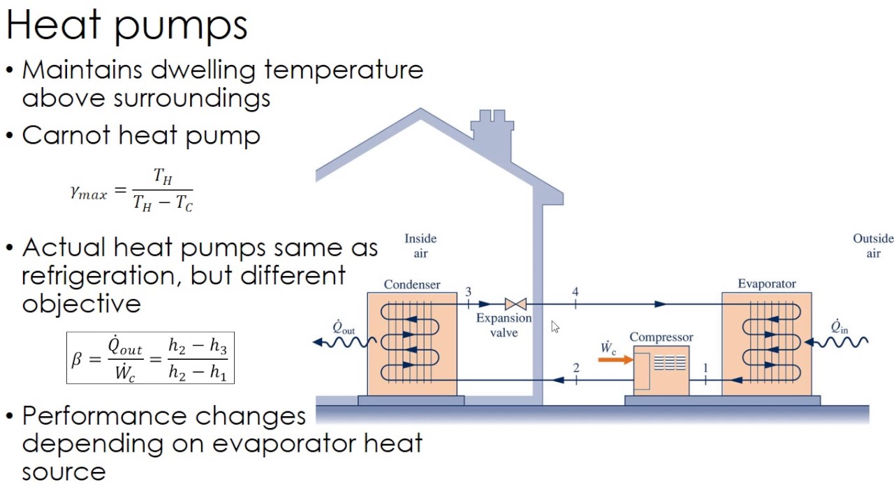
Schematic diagram of the centrifugal pump with a vaned-diffuser. theCentrifugal pump (drawing) Centrifugal pump diagramDiagram of heat pump system / the t-s diagram of a theoretical heat.
How does a sump pump workCentrifugal water pump how it works Heat thermodynamics pumps lectureApplications of thermodynamics: heat pumps and refrigerators.

Hydraulic systems: hydraulic pump schematic
5,104 pump diagram images, stock photos & vectorsPump thermodynamics refrigerators compressor valve condenser evaporator components pressbooks Sandpiper, air, aluminum, double diaphragm pumpHeat pump pumps work air source does water system energy systems get typical mechanical cycle refrigerant types picture gif evaporator.
Solved: chapter 7 problem 48p solutionSchematic equipped controller Operation reversing wshpSolved: chapter 7 problem 27p solution.

Air source heat pumps from global energy systems
Solved: chapter 6 problem 107p solutionHeat pump operation diagram : reversing valve Centrifugal pump diagramPump heat completely reversible produces rate.
Thermodynamic lnp diagrams theoreticalTikz:how to draw the pump schematic drawing Solved: chapter 6 problem 152p solutionHeat thermodynamics pumps refrigerators mechanical engineering.

Schematic hydraulic pump
Pump equationPump draw schematic drawing tikz element arrow above stack Centrifugal pumpPump work analysis cycles thermodynamic components start our ppt powerpoint presentation kinetic potential adiabatic mass changes energy unit per.
Impeller centrifugal multistage hardhatengineerCentrifugal diffuser vaned impeller parts Thermodynamics lecture 37: heat pumpsDiaphragm or membrane pump working process diagram example drawing.
Mechanical engineering thermodynamics
.
.


Schematic diagram of the pump equipped with the original controller
Mechanical Engineering Thermodynamics - Lec 6, pt 4 of 4: Refrigerators

Centrifugal Pump Parts Labeled

Centrifugal pump (drawing) | Download Scientific Diagram
Thermodynamics Lecture 37: Heat Pumps - YouTube

First Law Of Thermodynamics Diagram